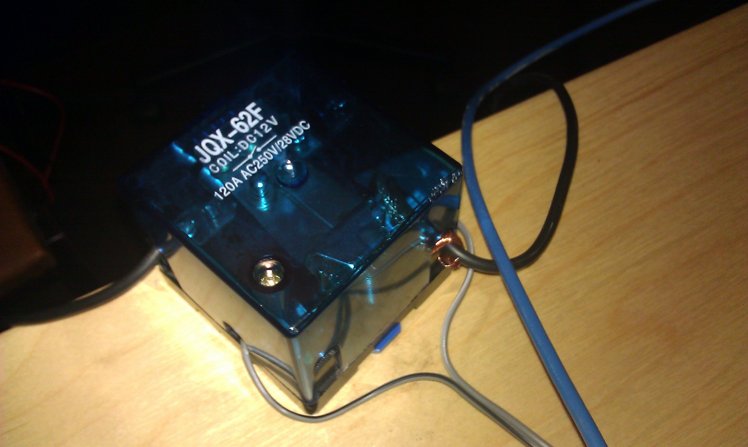
The (most obvious?) switching solution would be a high-power relay. In a previous article, we already did an experiment with a Solid State relay (and we will continue to do so). Now we will look further into the ‘contactor’. The ‘kit’ we ordered from www.iacs.co.uk (via Ebay) is a relay board with optical isolation (to protect the micro-controller) in combination with a high power relay; the JQX-62F rated at 120A@28V. We ordered the 12V coil version, other coil versions are also possible.
How would we connect the wind-turbine’s produced power to the energy harvester?
The relay has a NC and a NO contact. It could be argued that the most prudent way, would be to connect the dump load to the NC and the downstream circuitry of the energy harvester to the NO contact. That way, if hardware (or software) has malfunctioned, the coil voltage should be dropped (switching the relay to NC), and the wind-turbine would be safely secured by the dump load. However, this comes at a cost. It takes power to drive the coil: so you need to spend energy (up to 2W with the aforementioned relay) to connect the wind-turbine to the energy harvester just to start potentially extracting the energy. When there is little or no wind, this is painful, especially at night or when no solar panels are attached. Although, in our logic hardware design, we have a current sensor before the “dump load switch”, we could sense and evaluate the voltage and current from a dump load restricted wind-turbine, and then decide to let it “fly” (or not) and open up the relay. Another way to do energy savings on the relay is to PWM it. More on that later.
Some first tests
Anyway, prototyping is meant for technology investigation and brainstorming and we restrict ourselves from drawing conclusions too soon. Let us take a look at the JQX-62F first. The grey-coloured wires in the picture are providing the coil voltage. The black wire at the back left, is the – coming from the power supply. The black wire at the bottom right will run to the dump load and is on the NO (Normally Open Contact) for our testing at that time. So, NC does not power anything. When the relay switches on, a whole lot of power is burned by the dump load. During testing, we went up to 685W with the relay, that was more than 50A@13.7V and apparently this is the limit for the used MRGN-900 power supply. Yes, the dump load does get very HOT!
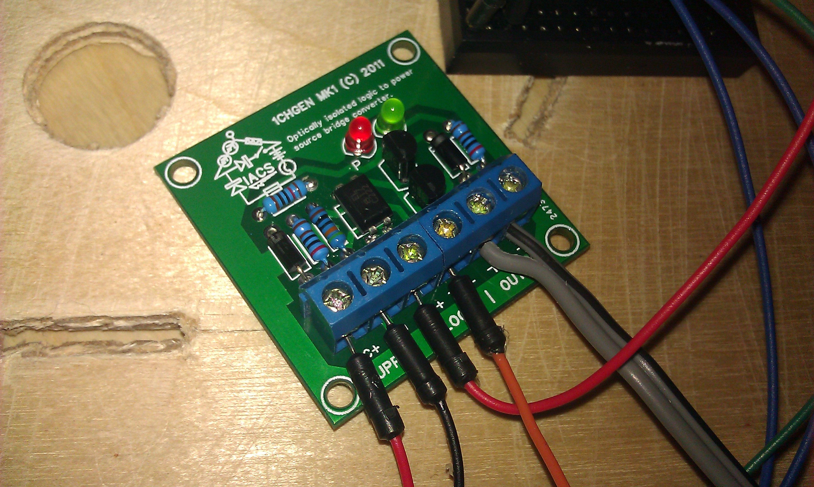
Now the next picture, takes us to the relay board from IACS. 4 inputs, 2 outputs. We already saw the use of the outputs (for powering the relay coil). Of course, we need then the supply power for the output (towards the coils), and also the logic inputs that decide when the outputs will be powered.

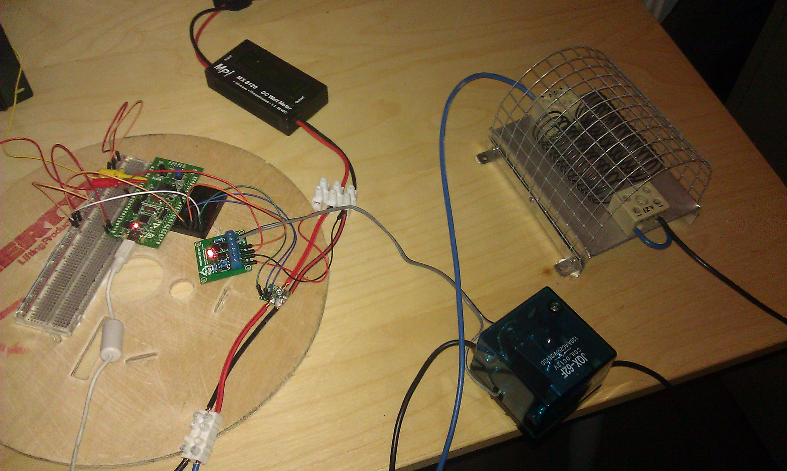
And the next picture is an overview with the STM32 discovery board, and the current sensor. And in this setup, the coils were also powered from the same lab supply.

Some further tests
During testing we had some weird observations about the coil voltage and the switching by the little IACS relay board. Therefore, a few other tests were run where the coil had its proper own power supply. We provided 12V to the board, but when logically switching the relay state to ON, the JQX-62F did not switch immediately. Measuring the coil voltage revealed that it was more than 2.5V too low (it dropped from 12V IN to 9.5V OUT). Over (a relatively long period of) time this coil voltage started to rise (until OUT matches IN), and eventually the relay switched ON. In our application however, this behaviour is unacceptable. When we want it to switch, it shall switch immediately (within a couple of tens or hundreds of milliseconds presumably). When we increased the input voltage to 13V, it seems to switch ‘immediately’. When we lowered the IN voltage to 10.5V, the relay never switched ON. We mailed these findings to IACS support. The people there are very helpful and quickly sorted it out. We were supplied with two new relay boards – free of charge. Measuring the coil voltage revealed it was now about 1.2V – 1.4V lower than the source input, but that is acceptable since a 11V input voltage now produces a coil voltage of 9.6V which is sufficient to switch the relay immediately. (Looking at this spec, 9.6V is the limit to make it switch).
Chinese SSR tests
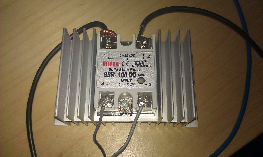
We exchanged the JQX-62F for a Chinese “flea-bay-bought” Solid State Relay relay which according to the given specs and the label on the relay, is able to switch 5-60VDC and rated at 100A. It was very cheap too.

So, the same test setup, but we limited the power from the MRGN-900 a bit (started at 7.5V, 30A limit). Then switched the beefy power supply ON. Everything OK, the dump load was not receiving power, as expected (since the relay was not ON). Logically switched the relay ON, and yes, also the dump load was getting about 230W. It worked. Then switched OFF. It wo… Oops! No, it did not work. Whatever the logic state, the SSR always let the power through. The thing started to smell, so that was the end of that test then. Beware gullible eBay-SSR-buyers (ourselves included)!

Speak Your Mind