The energy harvester application needs to be able to determine current flows and volt charges in order to take the right decisions about charging and dumping.
The micro-controller’s ADC unit is able to translate the analogue signal from the sensor into a quantified entity, a number if you wish. Internally, the device current is limited to 40A. Consequently, for prototyping purposes, we decided to experiment with the AttoPilot Voltage and Current Sense Breakout board (90A version). 40 Amps means that the connection wires should also be thick enough. (The thicker the wire, the less resistance, the less chance the wire goes up in flames).
Unfortunately, this proved to be too difficult to solder that correctly. Cfr pictures below. It works, but probably cannot withstand extended periods of 40A load.
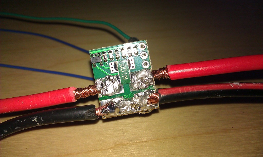
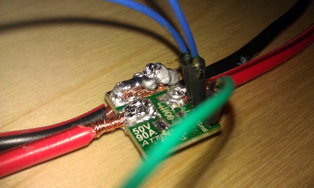
Fortunately, there is another way to do this: the DEANS connector. That way it looks a lot cleaner. Note, that we did not solder the female connector, but the male connector, because it was a better fit for our bread-boarding, but we might need to rethink it later on.
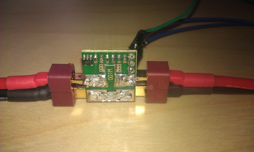
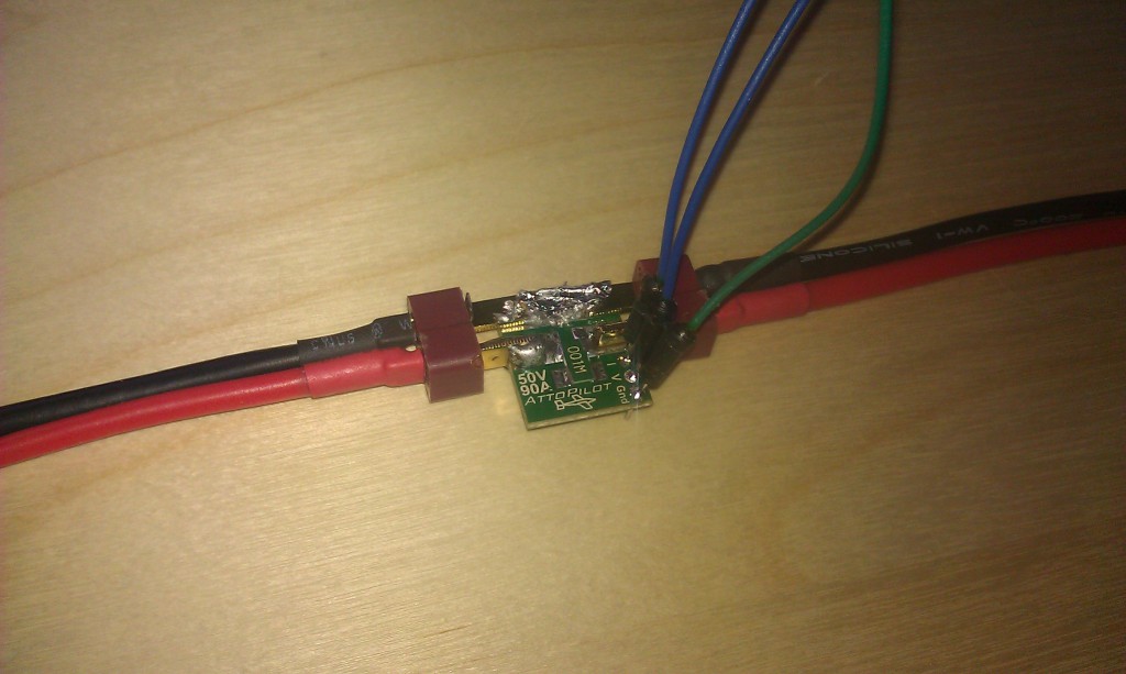
Current sensing works in the direction of the ‘aeroplane’: Iin to Iout, from left to right on the pictures. The sensor is self-powered and returns its measurements on 3 pins: Ground, I-measure and V-measure. We attached it to a breadboard which was hooked to the STM32 value line discovery board. At this time, we have UART, GPIO and ADC drivers up and running. A simple prototype protocol was developed and implemented which allows us to read out the measured ADC values via the serial connection over USB. So the laptop powers the discovery board, and the hefty power supply pumps DC power to the halogen lamp. An important issue to note is that the ADC reference voltage on the discovery board is not 3.3V but lower: somewhere between 2.9V and 3.0V, and it drifts a bit under influence of temperature. Hence, we maybe need to think about getting a stable calibration reference value.
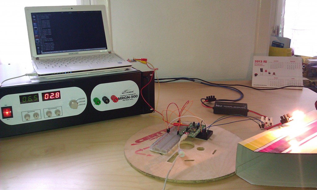
After building up our confidence in the solder, we exchanged the 12V halogen lamp for a dump load, and tried some higher power readouts. The highest output my power supply could manage – taking into account the used dump load – was 24V and 30A. Volt readings were OK, but Amperage readings were inaccurate (up to 3A variation) probably because a series resistor on the I-readout pin is missing.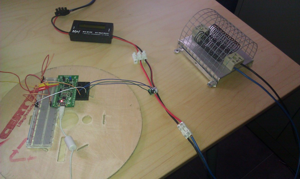
During these tests, nobody was injured. Not even a bit of smoke was observed, hence the board is still in pristine order to undergo some more tests later on.

Speak Your Mind