Switching power between battery and dump load is an important functionality of a charge controller. Switching fast by means of PWM allows for efficient battery charging: the battery (bank) is charged with an appropriate algorithm (bulk, absorption, float, pulse) while unnecessary energy is diverted to a dump load. Since relays are not well-suited for fast PWM switching, we use two SPST mosfet channels: one to battery and another one to dump load.
In experiment 1 we have charged a battery with one channel (low-side switching). In another post we have discussed various dual-channel PWM configurations (edge- or centre-aligned, same or different polarity). So now we are ready to combine things…
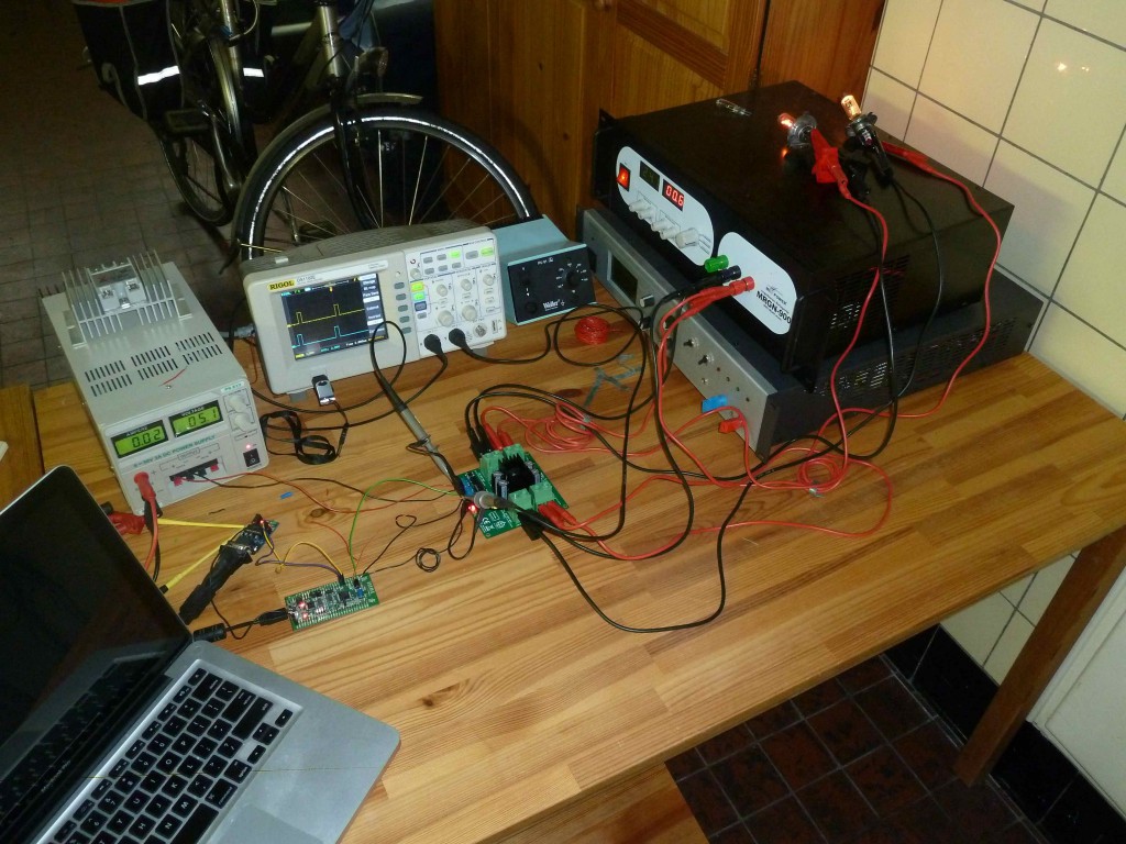
Experiment 2: switching power to two lamps (low-side switching)
In this experiment – just to keep things simple – we avoid switching inductive loads (dump load, battery). Our targets are two resistive lamps:
- channel 1: a 250W halogen lamp for a projector, and
- channel 2: a 90W truck bulb.
Here are the numbers at 24V:
- channel1 100% PWM (so just ON), channel2 0% (OFF): 11.2A => R=U/I => R=24V/11.2A => R=2.14 Ohm
- channel1 0%, channel2 100%: 1.7A => R=14.12 Ohm
- both channels 100% PWM: 13A => Rtotal = 24V/13A => Rtotal= 1.85 Ohm
Now, let us verify the last result (Rtotal = 1.85 Ohm) with Ohm’s law for parallel circuits: Rt = (R1*R2)/(R1+R2) = (2.14*14.12)/(2.14+14.12) = 1.86 Ohm which is ~ 1.85 Ohm.
In next test we compare two different PWM configurations when the lamps are PWM-ed at 50%:
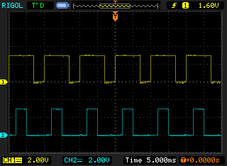
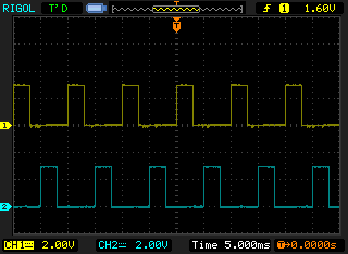
- both channels 50%, PWM left edge-aligned, same polarity: 7.5A
- both channels 50%, PWM left edge-aligned, different polarity: 7.5A
Surprisingly (or not) the PWM configuration doesn’t make any difference. But if we verify with theory:
- same polarity (50% (ch1+ch2)): I=U/R => I = 24V/Rt in which Rt = (R1*R2)/(R1+R2) = (2.14*14.12)/(2.14+14.12) = 1.86 Ohm => I = 12.90A/2 = 6.45A (<7.5)
- different polarity (50% ch1 + 50% ch2): (24V/R1)/2 + (24V/R2)/2 = 5.6A + 0.85A = 6.45A (<7.5A)
So in this case PWM configuration doesn’t make any difference BUT the current output is less! This makes sense though because the channel is switching on and off, and the resistance of a wire is lower when it isn’t hot. Thus, we did our calculations with resistances that are a little too high. This is confirmed by next test:
- ch1 0%, ch2 50%: 0.9A => R = (24V/0.9A)/2 = 26.67 Ohm / 2 = 13.35 Ohm which is lower than 14.12.
Experiment 3: switching power to dumpload and/or battery
In this setup our targets are lamp and battery. A diode prevents current flowing from battery to dump load (something we won’t have in our charge controller). Here we investigate the case in which both channels have a duty cycle of 30% at 15V. Channel 1 is the battery, channel 2 the dumpload:
- ch1 30%, ch2 0%: 2.3A => battery resistance = (15V/2.3A)/3.33 = 1.96 Ohm
- ch1 0%, ch2 30%: 5.5A => dump load resistance = (15V/5.5A)/3.33 = 0.82 Ohm
Given these resistances, we can now study the impact of various PWM configurations (always 30% duty cycle):
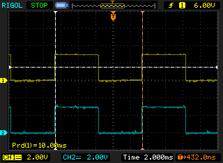
- left edge-aligned, same polarity: 7.3A. Theoretical verification: 15V/((1.96*0.82)/(1.96+0.82)) = 7.2A (~7.3).
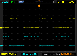
- left edge-aligned, different polarity: 8.3A. Theoretical verification: (15V/1.96Ohm)/3.33 + (15V/0.82Ohm)/3.33 + 0 = 7.8A (<8.3A).
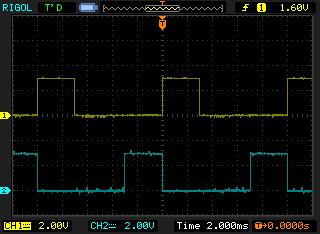
- centre-aligned, same polarity: 7.4A (note: the figure shows different duty cycles)
- centre-aligned, different polarity: 8.9A
Theory and practice are harder to match because of the dynamic nature of the test setup:
- 2 inductive loads (well, a battery is a capacitive load with inductive characteristics), and
- a battery that is being charged during all (sub-)tests (this might change its resistance).
We have also found that charging a battery is not linear i.e. at the start of a test the battery consumes a lot more energy.
Discussion
We have seen several PWM configurations but which one is most useful for our application?
Before we answer this question, it is interesting to list our goals again.
The main goal of a charge controller is safe and efficient battery charging. Depending on battery state, an optimal charge method is selected that determines when and how much energy is delivered to the battery.
A supplementary goal is safety of the whole system including wind turbine, solar panels etc. When power is abundant, solar panels can just be disconnected but, at higher wind speeds, a wind turbine requires a load (in order to control it and electro-mechanically prevent over-speeding). This load can’t always be the battery (as this depends on battery charge level and battery specs), and therefore we need a dump load. Note, that always braking is not good since the wind turbine should be able to start-up as well at lower wind speeds.
Here we have two channels: one to battery and one to dump load. The goal of the former is safe and efficient charging, the goal of the latter is to burn excess energy and brake the wind turbine.
So which PWM configuration(s) will support us best in writing a decent control algorithm?
More power to battery means:
- increasing battery duty cycle, and
- possibly decreasing dump load duty cycle.
And vice versa. Probably the PWM configuration doesn’t really matter: sensing volts and amps will tell us how the system evolves and how to react. The control algorithm should take care (PID control?).
Centre-aligned has a small advantage over edge-aligned: when changing duty cycle the transition is more smooth. High polarity has preference over low polarity because by default the channel is OFF.
Experiments will tell us more, for the moment we simply stick to edge-aligned.

Speak Your Mind